

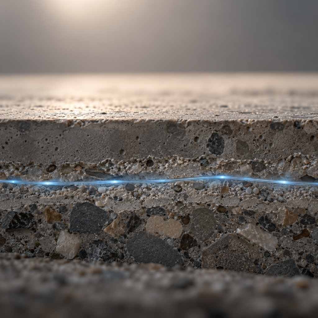
Fiber-optic monitoring can resolve calculated crack widths in the micrometer range, distributed over hundreds of meters of structure rather than at a handful of discrete points. Christoph Monsberger, co-founder of ACI Monitoring, explains in this interview how distributed fiber-optic sensing works, how it was deployed across the Brenner Base Tunnel, and why the technology is not the right answer for every project.
What sets fiber-optic monitoring apart from point sensors
The core advantage of fiber-optic sensing is that the location of a future defect does not need to be known at installation. The fiber acts as a kind of nervous system for the structure, capturing strain continuously along its entire length instead of at discrete points.
“I have an optical fiber and it acts as a kind of nervous system of the structure. That means an emerging defect is detected with very high spatial resolution and can then be quantified numerically.” Christoph Monsberger, ACI Monitoring
This matters most for structures that have reached their calculated design life or are operating under higher loads than originally planned. According to Monsberger, extending service beyond the design life, or under significantly higher utilization, should only happen with reliable monitoring systems in place to safeguard operational safety.
How the cable and measurement unit work
At the core of the technology is an optical fiber borrowed from telecommunications, with an outer diameter of 0.25 millimeters and a core just 9 micrometers wide, thinner than a human hair. For construction use it needs protective layers: plastic coating, stainless steel tubing known as fiber-in-metal-tube, or reinforcement made of steel or glass-fiber-reinforced plastic, depending on the application.
In new construction, the cable is ideally embedded directly in the concrete, which produces a perfect bond between structure and sensor. For existing structures, cables can also be applied afterward, for example by milling a shallow groove of a few millimeters into the surface, or for short-term use, simply bonded onto concrete, steel, or plastic.
- Fiber core diameter: 9 micrometers
- Outer diameter with protective coating: 0.25 mm
- High spatial resolution mode: one strain value every 2 mm, range up to 100 m
- Long-range mode: up to 25-50 km, resolution 0.2-0.5 m per strain value
How the measurement actually works
An interrogator couples a light pulse into the fiber. Because glass is never 100 percent pure, the pulse scatters at countless points along the fiber. A very small fraction of that backscatter travels back to the measurement unit, where it is analyzed for strain, temperature, or vibration.
Three distinct systems exist: Distributed Strain and Temperature Sensing, combining strain and temperature measurement, Distributed Temperature Sensing alone, based on Raman backscatter and insensitive to strain effects, and Distributed Acoustic Sensing for vibration monitoring, used for example to locate leaks along pipelines. For structural monitoring, combined strain and temperature sensing is the most relevant system, since reliable temperature compensation is essential for usable strain data.
A key practical advantage: the interrogator does not need to sit at the measurement location itself. It can be placed outside a tunnel, below a bridge, or in an easily accessible maintenance building, connected via cable to the actual sensing sections. That means no restriction on the structure’s ongoing operation.
Crack widths in the micrometer range
In a recent project on an existing bridge, ACI Monitoring installed a sensor network across roughly 100 meters, specifically to catch new cracks forming in the structure early, ahead of the next scheduled visual inspection. Load tests on site allowed the opening and closing of cracks to be observed directly.
“And there we can definitely resolve significant calculated crack widths in the micrometer range with this technology.” Christoph Monsberger, ACI Monitoring
Over a full annual cycle, the data also revealed thermal crack breathing, openings ranging from a few micrometers up to the hundredth-of-a-millimeter range, not structurally relevant on their own, but clearly resolvable at roughly 50 times the measurement noise. Notably, at this bridge the thermally induced strain over a full year was about ten times larger than the deformation produced by the controlled load test itself. Anyone setting alarm thresholds needs to understand this natural annual cycle, otherwise false alarms will eventually make a monitoring system irrelevant to its own operators.
The Brenner Base Tunnel as a reference project
At the Brenner Base Tunnel, ACI Monitoring says it realized one of the largest fiber-optic strain monitoring projects in the world: nearly 40 kilometers of sensor cable and 60 kilometers of connecting lines, installed across roughly 25 percent of the tunnel’s total length. The sensors were embedded in precast concrete segments already at the factory, before the segments were assembled into continuous rings during tunnel boring.
The measurement unit itself sits several hundred meters to up to a kilometer away from the actual sensing point, connected via cable, in sections with particularly high rock overburden and difficult geological conditions.
Common mistakes and why timing matters
According to Monsberger, the biggest source of error is not the sensor technology itself but the organizational split between the construction team and asset management. When monitoring is only considered after project handover, critical information gets lost. His clear recommendation: consider monitoring at the earliest possible moment in the planning phase, not once the structure is already finished.
Tunnel projects add another constraint: interruptions to tunnel boring are extremely costly, so sensor installation has to be built into the construction sequence in a way that minimizes impact on progress. One concrete cautionary example from practice: an anchor-head monitoring system had its alarm thresholds set incorrectly at first, triggering so many false alarms that the system was eventually switched off entirely, despite significant public funds having been invested.
When fiber-optic monitoring actually pays off
Monsberger is cautious about selling fiber-optic monitoring as a universal solution. The sensor has to match the object and the damage mechanism, and sometimes a conventional sensor costing a few hundred euros is entirely sufficient. Distributed fiber-optic systems earn their value when the location of future damage is unknown, for example crack formation on a bridge with no known weak points, or anchor systems where the force distribution along the full anchor length matters, not just at the anchor head.
For other problems, such as slope movement or settlement at bridge piers, GNSS methods, classical geodesy, or hydrostatic leveling systems may be the cheaper and perfectly adequate solution. Deciding correctly always requires combining sensor expertise with domain knowledge from structural engineering, geotechnics, or soil mechanics.
How accurate is fiber-optic monitoring for crack detection?
In one documented bridge project, calculated crack widths in the micrometer range were resolved, at roughly 50 times the measurement noise. Usable spatial resolution depends on range: over short distances up to 100 meters, a strain value every 2 millimeters is possible, while at 25 kilometers range the resolution is around 0.5 meters.
Does fiber-optic monitoring need to be planned in at the design stage?
Not strictly, but it is strongly recommended. Only when monitoring is considered during planning can the sensor network be properly integrated into the construction sequence and structural design. For existing structures, monitoring is typically deployed reactively, once a damage case or a specific risk has been identified.
Is fiber-optic monitoring the right choice for every structure?
No. The sensor needs to match the specific damage mechanism. For problems without a known damage location, such as new cracking on a bridge or anchor systems, fiber-optic sensing offers advantages over point sensors. For other questions like slope movement or pier settlement, classical geodetic methods can be sufficient and more cost-effective.
Literature
- ACI Monitoring
- Montoring with Accelerometers (Irmos)
- Monitoring with Satellites (InSAR)
- Distributed fibre optic sensing in geotechnics and tunnelling – Excessive data generation or valuable information for construction and operation?
- Entwicklung, Umsetzung und Betrieb des geodätischen und faseroptischen Monitoringsystems der S-Bahn-Überbrückung am Bahnhof Stuttgart S21
- Implementation of an enhanced fiber optic sensing network for structural integrity monitoring at the Brenner Base Tunnel
- Large-scale distributed fiber optic sensing network for short and long-term integrity monitoring of tunnel linings
- Distributed fiber optic sensing along driven ductile piles: Design, sensor installation and monitoring benefits